Low-Temperature Heating Layouts for Deep Retrofit Projects
Across the Netherlands, the energy transition is accelerating. With the government phasing out natural gas connections and encouraging all-electric solutions, homeowners undertaking a whole-home renovation are increasingly turning to low-temperature heating systems paired with a heat pump. A deep retrofit that delivers true energy efficiency must treat the heating layout as a carefully orchestrated system, not just a boiler swap. This article explores the principles, practical Dutch heating design strategies, and must-know considerations for integrating low-temperature emitters into your renovation plan.
Why Low-Temperature Heating Matters in Dutch Renovations
Traditional Dutch homes rely on gas boilers (cv-ketels) that heat water to 70–90°C and push it through radiators. In contrast, a heat pump reaches its optimal coefficient of performance (COP) when the supply water temperature stays below 55°C – ideally between 35°C and 45°C. For every degree you lower the flow temperature, the heat pump works more efficiently, translating directly into lower electricity bills. In a deep retrofit, you have the opportunity to rethink the entire heat distribution system so that it can deliver comfort with water temperatures that make the heat pump shine.
Low-temperature heating is also the gateway to future-proofing. Even if you start with a hybrid setup (a heat pump combined with an HR-ketel), designing the distribution for 50°C or below means you can switch to a full-electric arrangement later without ripping out pipes or radiators. Government incentives like the Investeringssubsidie Duurzame Energie (ISDE) further reward installations that meet low-temperature criteria, making this approach financially attractive.
Key Concepts for a Low-Temperature Heating Layout
Supply, Return and ΔT
In a classic high-temperature system, the temperature difference between supply and return (ΔT) can be as wide as 30–40°C. Low-temperature circuits aim for a tighter ΔT, around 5–10°C with underfloor heating or up to 15°C with low-temperature radiators. A smaller ΔT means a higher flow rate, which influences pipe diameter selection. Understanding this relationship is the foundation of any well-engineered layout.
Emitter Types and Their Temperature Ranges
- Underfloor heating (vloerverwarming): optimal supply temperature 30–40°C, large surface area delivers radiant warmth.
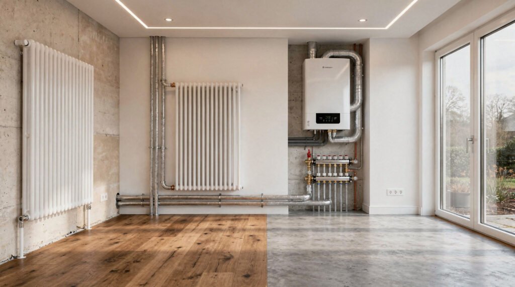
- Low-temperature radiators (LTV-radiatoren): designed with enhanced convection fins, operate at 45–55°C and can replace old panel radiators.
- Fan-assisted convector radiators: can work with water as low as 35°C, combining quick response with small form factor.
- Wall and ceiling heating: less common but equally effective, working between 30°C and 40°C.
Planning the Layout: From Heat Loss to Pipework
Step 1 – A Precise Heat Loss Calculation (Transmissieberekening)
A deep retrofit is only as good as its thermal shell. Before you sketch a single pipe, have a professional perform a room-by-room heat loss calculation according to the ISSO standards adopted in the Netherlands. This calculation uses the upgraded insulation values (Rc-waarden), triple glazing with U-value around 0.8 W/m²K, and airtightness (qv;10) after renovation. With a well-insulated envelope, the heat demand per square metre drops dramatically – often below 40 W/m² – making a low-temperature supply viable even on the coldest winter days.
Step 2 – Selecting the Right Emitters for Each Room
In a typical Dutch terraced house (tussenwoning), you might combine underfloor heating on the ground floor with low-temperature radiators in the bedrooms. Underfloor heating excels in open-plan living areas because it provides uniform comfort without taking up wall space. For bathrooms, a combination of underfloor heating and a low-temperature towel radiator (design temperature 50/40/20) works well. Where underfloor heating is not possible – for example, in a second-floor room with a wooden subfloor that cannot bear extra screed weight – slimline fan convectors offer a high-output, low-temperature alternative.
Step 3 – Zoning and Hydraulic Setup
The Netherlands often adopts an “open verdeler” (low-loss header) configuration that decouples the primary heat pump circuit from the secondary emitter circuits. This arrangement prevents flow rate conflicts and allows the heat pump to maintain its ideal ΔT. A typical layout for a fully renovated home includes:
- Heat source (heat pump) with its own circulation pump, feeding a buffer tank or hydraulic separator.
- Primary manifold splitting into multiple secondary circuits: ground‑floor underfloor heating, upper‑floor radiators, and domestic hot water priority.
- Each secondary circuit gets its own pump and a thermostatic mixing valve to precisely control the supply temperature according to the emitter type.
Buffer tanks play a crucial role in low-temperature layouts, providing thermal inertia that minimises short cycling during mild weather and enabling proper defrost cycles for air-source heat pumps.
Comparing High-Temperature vs. Low-Temperature Design
Aspect: Typical heat source
Traditional High-Temperature (70–90°C): Gas boiler (cv-ketel)
Low-Temperature Retrofit (35–55°C): Heat pump (all-electric or hybrid)
Aspect: Emitter size
Traditional High-Temperature (70–90°C): Compact panel radiators
Low-Temperature Retrofit (35–55°C): Large-area underfloor, oversized LTV radiators
Aspect: Flow rate
Traditional High-Temperature (70–90°C): Low (high ΔT)
Low-Temperature Retrofit (35–55°C): High (low ΔT) – requires careful pipe sizing
Aspect: Thermal comfort
Traditional High-Temperature (70–90°C): Convective heat, can feel drafty
Low-Temperature Retrofit (35–55°C): Radiant heat, stable and comfortable
Aspect: System efficiency
Traditional High-Temperature (70–90°C): Boiler efficiency ~95% (HR)
Low-Temperature Retrofit (35–55°C): Heat pump COP 3–5, depending on flow temperature
Aspect: Retrofit complexity
Traditional High-Temperature (70–90°C): Simple pipe re-use
Low-Temperature Retrofit (35–55°C): Often needs new distribution manifolds, larger pipes, insulation
Heat Pump Integration: The Core of Efficiency
A heat pump performs poorly at high flow temperatures. Every extra degree matters: a typical air-to-water heat pump running at 35°C may achieve a COP of 4.5, but at 55°C the COP can fall to 2.5. That is nearly 45% more electricity for the same heat output. Designing the entire distribution system for the lowest possible temperature is therefore the most effective energy-efficiency measure in a retrofit.
In the Dutch context, a hybride warmtepomp can be a smart intermediate step. It keeps the existing HR-ketel as a backup for the very coldest days, while the heat pump covers 70–80% of the annual heating load. Even then, lowering the base supply temperature as much as possible yields immediate savings. The layout should always be prepared for a future full-electric switch by ensuring the emitters can still deliver enough heat if the gas boiler is removed.
Design Temperatures for Different Emitter Types (Practical Examples)
Emitter Type: Underfloor heating (wet system)
Recommended Supply (°C): 35
Return (°C) at Design Day: 30
Room Temp (°C): 20
Emitter Type: Low‑temperature radiator (type 22)
Recommended Supply (°C): 45
Return (°C) at Design Day: 35
Room Temp (°C): 20
Emitter Type: Fan convector (ventilatorconvector)
Recommended Supply (°C): 35
Return (°C) at Design Day: 30
Room Temp (°C): 20
Emitter Type: Bathroom towel radiator (LTV)
Recommended Supply (°C): 50
Return (°C) at Design Day: 40
Room Temp (°C): 24
Emitter Type: Wall heating
Recommended Supply (°C): 33
Return (°C) at Design Day: 28
Room Temp (°C): 20
These temperatures assume a well-insulated building. If your renovation achieves an Rc of 4.5 for walls and 6.0 for roofs, these supply temperatures are realistic for a Dutch winter day of -10°C outside.
Pipe Sizing and Distribution Efficiency
Low-temperature circuits require larger volume flows. A rule of thumb: doubling the flow rate halves the temperature drop. This has direct consequences for pipe diameter. In existing homes, old 15 mm copper pipes may create too much resistance. During a whole-home renovation, replacing main distribution lines with 22 mm or 28 mm PEX-AL-PEX or multi-layer pipe ensures low pressure drop and future adaptability. Use pre-insulated pipes when running them outside the thermal envelope, such as between the outdoor heat pump and the indoor unit.
Manifolds (verdelers) are essential for underfloor heating systems. Modern manifolds with integrated flow meters allow exact balancing, guaranteeing that each loop receives the calculated flow. For radiator circuits, a central distribution manifold with thermoelectric actuators enables per‑room control without interfering with the heat pump’s flow stability.
Control Strategies for Maximum Efficiency
Weather Compensation (Weersafhankelijke Regeling)
A heat pump system should never run at a fixed high temperature. A weather-compensated controller adjusts the supply water temperature based on the outdoor temperature. As it gets milder outside, the system lowers the flow temperature, boosting the COP dramatically. Set the heating curve (stooklijn) to the lowest possible supply that still meets comfort – typically beginning at 35°C at 0°C outside and ramping up to the design temperature at -10°C.
Room Thermostats and Zone Valves
While zoning can save energy, excessive use of on/off zone valves can cause the heat pump to short cycle if the system volume is too small. The best practice is to keep at least one large zone (like the living area) permanently open as a “heat sink” and use electronic thermostats that modulate valves rather than simply opening and closing. A buffer tank of sufficient volume (30–50 litres per kW of heat pump capacity) provides the necessary hydraulic decoupling.
Night Setback Considerations
With a high-mass underfloor heating system, setbacks are counterproductive because the floor takes hours to recover, often forcing the heat pump to work at higher temperatures during the morning boost. For low-temperature retrofits, a constant temperature or a gentle setback of 1–2°C is recommended. If you use fan convectors that respond quickly, a deeper setback can be applied.
Practical Tips for Dutch Homeowners During a Renovation
- Insulate first. A low-temperature heating system will fail to deliver comfort if the thermal envelope is leaky. Aim for at least label A++ after renovation. Address wall, roof, floor insulation and triple glazing before the heating design.
- Involve a certified installer early. Look for a professional with a “warmtepomp” certification (e.g., STEK or BRL 6000-00) who understands low-temperature design, not just boiler replacements.
- Consider future heat demands. If you later extend the house or convert the attic, add spare capacity in the manifold and buffer tank. This avoids costly modifications later.
- Don’t forget domestic hot water (DHW). A separate heat pump boiler or a combi-unit with a high-efficiency heat exchanger can produce DHW at 55°C while the heating circuit runs at much lower temperatures.
- Hydronic balancing is non-negotiable. A system that is perfectly designed but not balanced will result in cold spots, noise, and reduced efficiency. Invest in a professional balancing procedure after installation.
- Monitor performance. Install a heat meter or use the heat pump’s built-in energy monitoring to track the seasonal COP (SCOP). This helps verify that the design intentions are met in real operation.
Integrating Renewable Energy and Future-Proofing
A low-temperature layout also makes your home a good match for solar photovoltaic panels. Electricity produced during sunny, mild weather can directly power the heat pump exactly when the required supply temperature is lowest. Pairing the system with a smart energy manager helps maximise self-consumption. And if your neighbourhood later connects to a low-temperature district heating network (warmtenet), your internal distribution is already compatible, with no further renovation needed.
Common Mistakes to Avoid
- Reusing old micro-bore pipes. The high resistance severely limits flow, starving the emitters.
- Oversizing the heat pump without a buffer tank. Too-large capacity leads to frequent cycling and poor efficiency.
- Setting the heating curve too high. Installers sometimes use a safe, high setting that negates the low-temperature advantage.
- Neglecting airtightness. Uncontrolled air leakage drives up heat loss subtly but persistently, forcing the system to work harder.
- Ignoring sound requirements. An outdoor heat pump unit must comply with Dutch noise regulations (max 40 dB at the property boundary during night). Position it and select a model accordingly.
Conclusion
Designing a low-temperature heating layout for your deep retrofit is the smartest investment you can make in a whole-home renovation. It aligns perfectly with the Dutch ambition to eliminate natural gas and unlocks the full potential of a heat pump for superior energy efficiency. By combining a well-insulated envelope, carefully chosen emitters, correctly sized pipework, and weather-compensated controls, you create a future-proof home that delivers whisper-quiet, uniform warmth while cutting energy bills and CO₂ emissions dramatically.
Start with a thorough heat loss calculation, select emitters that thrive at 35–45°C, and never underestimate the importance of hydraulic balance. When done right, low-temperature heating is not a compromise – it is the most comfortable and sustainable way to heat a modern Dutch home.